Basically, electronic components mean any fundamental discrete object or physical thing that affects electrons or the fields they interact with is referred to as an electronic component in an electronic system. There are two types of components.
Passive Components
Electronic components that lack gain or directivity when in use are referred to as passive components. Additionally, they are dependent only on the power provided by the (AC) circuit to which they are connected. However, they can increase a voltage or current but cannot amplify. Two-terminal components like resistors, capacitors, and inductors are examples of passive components.
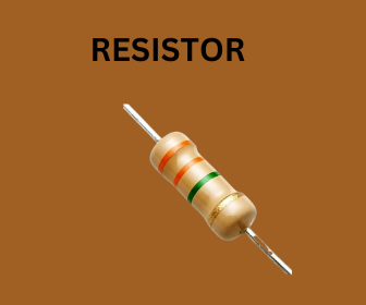
- Resistor:-
The term “Resistor” refers to a component with the property of resistance, which is an electronic element formed of resistive material that opposes the flow of current. A resistor is a two-terminal component. Zig-Zag lines between two terminals are used to symbolize a resistor. Because the resistor is not polarized, it can be connected from either side and has the same polarity on both sides. The resistor’s value is expressed in Ohm.
Classification of several resistor types:
- Linear resistor:- Linear resistors are those whose value varies as a function of temperature and voltage. When a current passes through most types of linear resistors, they cause a voltage drop across themselves. Fixed and variable resistors are the two fundamental forms of linear resistors.
- Fixed resistor:- Resistors with a set value are known as fixed resistors. One of the most often used types of resistors is fixed resistors. To establish the proper conditions in a circuit, fixes resistors are utilized in an electronic circuit. Again fixed resistors are divided into some types like wire wound resistors, thin film resistors, and carbon composition resistors.
- Variable resistor:- A resistor whose resistance value may be changed is referred to as a variable resistor. A potentiometer with only two connected wires as opposed to three is simply described as a variable resistor. Types of the variable resistor are potentiometer, rheostat, and trimmer resistor.
Non-linear resistor:- Non-linear resistors deviate from Ohm’s law in that the electric current passing through them fluctuates in response to variations in applied voltage or temperature. Non-linear resistors come in a variety of forms, but the common ones are:
- Thermistors:- A particular class of variable resistors that can detect temperature changes is the thermistor. A thermistor’s resistance is inversely proportional to temperature.
- Varistor:- A varistor is a non-linear resistor made of a semiconductor and the current flowing through it does not depend linearly on the applied voltage across it. The most popular kind of varistor resistor is called a metal oxide varistor.
- Light-dependent resistor or photoresistor:- LDR or photoresistor is a light-controlled resistor. As the intensity of the incident light increases, the photoresistor resistance lower
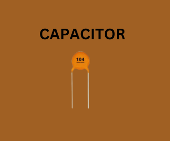
2. Capacitor:-
The Capacitor is a type of energy storage that interacts with AC and blocks DC. Electrical energy is frequently stored in it. The capacitor is made up of two conducting plates separated by a dielectric liquid. A capacitor is frequently used to add a time delay to a circuit, like in making a light blink. However, it can also be used to reduce noise in an audio signal or stabilize a circuit’s power supply.
Capacitor possesses the following properties-
- It fights against any voltage change in the circuit to which is connected.
- When it comes to energy storage, capacitors excel.
- It prevents DC.
- Circuits use capacitors as a noise filters.
- Harmonics blocker or eliminator for frequencies.
Types of capacitors:
- Ceramic capacitor:- These non-polarized capacitors have two or more layers of metal and ceramic that alternate with one other. Metal serves as the electrodes, and ceramic serves as the dielectric. This sort of capacitor often has a 3-digit code printed on the body to indicate the capacitance in Pico farads. The capacitors value is represented by the first two digits and the third digit indicates how many zeros should be added. “Disc Capacitors” is another name for ceramic capacitors.
- Electrolytic Capacitor:- When a big capacitance is required, these types of capacitors are typically utilized. An oxidized layer serves as a dielectric and covers the metal anode of electrolytic capacitors. Electrolytic capacitors are polarized. This means that when applying DC voltage to it, the proper polarity must be utilized. Simply put, the capacitor’s positive lead needs to be linked to the positive terminal, and its negative lead needs to be attached to the negative terminal. Depending on their dielectric, these capacitors are divided into three types listed below:
- Aluminum Electrolytic capacitors
- Tantalum Electrolytic capacitors
- Niobium Electrolytic capacitors
- Film Capacitor:- These are the most typical capacitors found in electronic devices. Film capacitors or plastic film capacitors are non-polarized. Here, the dielectric is an insulating plastic film. These capacitor electrodes might be made of reactive zinc metal or aluminum metal. They create a metalized film capacitor when they are applied to either one or both sides of the plastic film. A film capacitor can occasionally be created by covering the film with a different metallic foil. These are quite trustworthy, last a very long time, and have few tolerances. They also perform well in environments with high temperatures.
- Variable Capacitor:- These capacitors are non-polarized variable capacitance variety. For measuring capacitance, they use both moving and stationary plates. Typically, they are utilized in transistor radios, transmitters, and receivers.
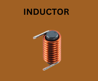
3. Inductor:-
An electronic component known as an inductor is made up of a coil twisted around a core. You can make an inductor by taking a wire and winding it around a coil. When a current is passed through a coil, a magnetic field surrounds it and stores energy. However, the magnetic field’s stored energy will oppose any change in the inductor’s current by alternating the inductor’s resistance. When designing a filter to reduce noise, for instance, resistance to change is a positive thing.
Classifications of inductors:
- Air Core Inductor:- The term “air-cored inductor” refers to an inductor that either completely lacks a core or has a core made of ceramic material. When a little amount of inductance is needed, these inductors are utilized. It does not have a core loss since there is no core. In contrast to inductors with a core, this type requires a greater number of turns from the inductor. As a result, a high-Quality factor is produced. Air core inductors are a common name for ceramic inductors. These inductors have a low inductance and a high reluctance path for the magnetic flux.
- Iron Core Inductor:- Iron makes up the core of this kind of inductor, as the name would imply. These inductors feature a low profile, high power, and high inductance value. However, their high-frequency capacity is limited. The filter circuit employs an iron-cored inductor to reduce ripple voltage. Additionally, it serves as a choke in industrial power supply, inverter systems, fluorescent tube lights, etc.
- Ferrite Core Inductor:- The core of this type of inductor is made of ferrite materials. The majority of ferrites are composed of XFe204. Where X represents transition material. There are two different categories for ferrites, Ferrites can be either soft or hard.
- Soft ferrite- Materials that can reverse their polarity on their own without the use of outside energy are called soft ferrites.
- Hard ferrite- These are permanent magnets. That is, even when the magnetic field is removed, their polarity will not change.
Active Components
Devices that can boost an electric signal and generate power are known as active components. In devices, an active component serves as an alternating current circuit. The device can increase power and voltage due to the fact that is powered by a source, this components can carry out their functions. An oscillator, transistor, or integrated circuit will be a part of any typical active component.
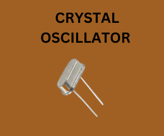
- Oscillator:-
An electronic device known as an oscillator operates on the oscillation principle, which describes periodic fluctuations between two objects caused by changes in energy. The Oscillator generates an uninterrupted, repeating, alternating waveform without any input. Basically, oscillators change the unidirectional current flow into an alternating waveform with the desired frequency, determined by the elements of their circuit. When two requirements, referred to as Barkhausen’s criteria are satisfied then the circuit will oscillate.
These two circumstances are:
- The loop gain must be unity or greater.
- The feedback signal feeding back at the input must be phase shifted by 360 degrees (which is the same as zero degrees).
An oscillator’s consistent waveform frequency is one of its characteristics. Oscillators come in a wide variety of forms, but they can be broadly divided into two groups: Harmonic oscillators (sometimes called linear oscillators) and relaxation oscillators
- Harmonic Oscillator:- In a harmonic oscillator, energy constantly flows from the active to the passive parts, and the feedback path determines the frequency of oscillations. Low-distortion sine-wave outputs are produced by harmonic oscillators.
- Relaxation Oscillator:- In a relaxation oscillator, energy is transferred between the active and passive parts, and the oscillation frequency is governed by the time constants involved in the charging and discharging processes. Non-sinusoidal waveforms, such as square, triangle, or sawtooth are produced by relaxation oscillators.
The most common varieties of oscillators are:
- Crystal Oscillator
- Wien Bridge Oscillator
- Hartley Oscillator
- Colpitts Oscillator
- Clapp Oscillator
- RC Phase Shift Oscillator
- Armstrong Oscillator
- Voltage Controlled Oscillator
- Tuned Collector Oscillator
2. Transistor:-
A semiconductor device known as a transistor can be used to conduct and insulate electric current or voltage. A transistor is a tiny device that is used to regulate or control the flow of electronic impulses. Transistor offers a wide range of functions, including signal modulation, voltage stabilization, amplification, switching, rectifying, and detection. Transistors have a high response rate and great accuracy, making them suitable for a wide range of digital and analog operations. Typically, three layers of semiconductor materials are used to create a transistor or more particularly, terminals that aid in carrying the current and establishing a link to an external circuit. The voltage or current provided to any one pair of a transistor’s terminals regulates the current flowing through the opposite pair of terminals.
The transistor has three terminals. These are:
- Base- This is utilized to turn on the transistor.
- Collector- It is the transistor’s positive lead.
- Emitter- It is the transistor’s negative lead.
Bipolar Junction Transistor and Field Effect Transistor are the two primary kinds of transistors.
- Bipolar Junction Transistor (BJT) :- Base, Emitter and collector are the three BJT terminals. A much larger flow of current between the collector and emitter terminal can be controlled by a very little current flowing between the base and emitter. Additionally, there are two varieties of BJT. These consist of;
P-N-P transistor: This transistor, which belongs to the family of bipolar junction transistors, has two p-type semiconductor elements within. These materials are separated by a thin layer of n-type semiconductor. In these transistors, holes make up the majority charge carriers while electrons make up the minority charge carriers.
N-P-N transistor: The NPN family of BJTs, which consists of two n-type semiconductor materials that are separated by a thin p-type semiconductor layer. The majority charge carriers on an NPN transistor are electrons, whereas the minority charge carriers are holes.
- Field Effect Transistor(FET):- The gate, source, and drain regions make up the three parts of FET. Field Effect Transistors are voltage-controlled devices. A current between the source and drain can be managed by the voltage at the gate terminal. FET is a unipolar transistor in which conduction is accomplished using either an N-channel FET or P channel FET. The input impedance of FET can range from several mega ohms to extremely high values. The terminals of FET are as follows:
Source – The terminal known as the source is where the majority of charge carriers are introduced into FETs.
Drain – The drain terminal is where the majority of charge carriers leave the field effect transistor. Gate – Diffusion between an N-type and a P-type semiconductor results in the formation of the gate terminal. As a result, an area of the PN junction that controls the carrier’s flow from source to drain is strongly doped.
Junction Field Effect Transistors (JFET) and Metal Oxide Semiconductor Field Effect Transistors (MOSFET) are two different types of FET transistors.
JFET:- A reverse-biased diode junction serves as the gate connection in a junction FET or JFET. A semiconductor channel makes up the structure and it can either be N-type or P-type. Then the channel is constructed with a semiconductor diode so that the voltage on the diode impacts the FET channel. The current flow is used to classify the two types of JFETs i.e. N-type or P-type. Weak signals are amplified using such transistors. JFETs are unidirectional.
MOSFET:- The fundamental purpose of transistors in circuits is to increase voltages. The gate, Source, and Drain are its three terminals. Between the gate and the channel of the MOSFET, there is an insulating layer. Typically, this is created from a layer of semiconductor oxide. The two kinds of MOSFETs are distinguished by their modes,
Depletion mode – The channel that is already existent allows MOSFET to function.
Enhancement mode – In this mode channel is induced by the gate voltage.
The cut-off region, saturation region, and ohmic region are the three operational regions of MOSFET. MOSFETs are bidirectional.
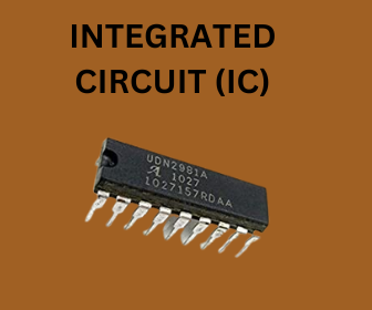
3. Integrated Circuit:-
The term “integrated circuit” or IC is also known as “microelectronic circuit”, “microchip” or “chip” refers to an assembly of electronic components that are manufactured as a single unit. Electronic components like resistors, capacitors, transistors, and diodes and their interconnections are connected on a thin semiconductor substrate (typically silicon). In addition to serving as a microcontroller or processor, an IC can also act as an amplifier, oscillator, timer, counter or logic gate. Every contemporary electronic gadget starts with an IC as its basic component. An IC uses several levels of abstraction. The IC’s semiconductor wafer, which has several layers, is delicate and has numerous complicated connections between them.
ICs have advanced significantly during the past 50 years, with quicker speeds, more capacity, and smaller sizes. Today’s ICs, which can fit billions of transistors and other components on a single little piece of material is incredibly sophisticated when compared to earlier models. Individual components are directly implanted in the silicon crystal of the modern IC rather than being mounted on it. Depending on the application, ICs can be linear or analog, digital, or a hybrid of the two.
- Analog Integrated Circuit – The term “analog ICs” refers to ICs that can handle a wide range of signals continuously. Operational amplifiers, often known as op-amps are a type of analog IC that is extensively used. They are similar to differential amplifiers but have much higher voltage gains. Compared to digital ICs, it has a significantly lower number of transistors and computer simulation tools are used to create analog application-specific integrated circuits (analog ASICs)
- Digital Integrated Circuit – Digital ICs are integrated circuits that only function at a limited range of defined levels rather than at several levels of signal amplitude and they are created utilizing a variety of flip flops, multiplexers, digital logic gates, and other electronic circuitry. These logic gates function with digital or binary inputs such as 0 (low or false or logic 0) and 1 (high or true or logic 1).
- Mixed Integrated Circuit – Mixed integrated circuits are created by combining analog and digital integrated circuits on a single chip. These ICs serve as clock/timing ICs, digital-to-analog converters, and analog-to-digital converters. Because of advancements in integration technology, it was possible to combine RF, numerous analogs and digital functions on a single chip to create the mixed or hybrid signal systems-on-a-chip.
More Posts: